
Free Ohm’s Law Calculator – Voltage, Current, Resistance & Power
Instantly solve electrical circuit values using Ohm’s Law formulas
This Ohm’s Law Calculator helps you accurately calculate voltage (V), current (I), resistance (R), and electrical power (P) by entering any two known values. Designed for quick and reliable circuit analysis, the tool applies standard electrical formulas to deliver instant, precise results.
Ideal for students, electricians, engineers, and electronics hobbyists, this free calculator simplifies electrical problem-solving without manual calculations. Whether you're analyzing DC circuits, checking component values, or learning electrical fundamentals, this tool provides clear results with no registration required.
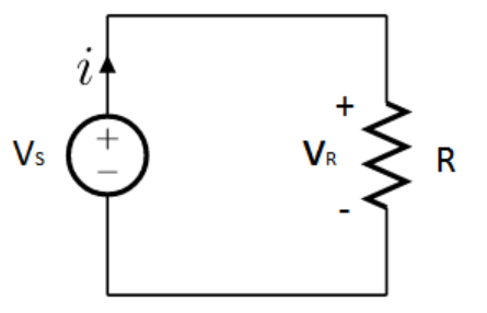
Visual representation of Ohm's Law circuit
Calculation Results
Voltage
Current
Resistance
Power
Ohm's Law Formulas
Voltage Formula
Voltage equals current multiplied by resistance
Current Formula
Current equals voltage divided by resistance
Resistance Formula
Resistance equals voltage divided by current
Power Formula
Power equals voltage multiplied by current
Visual Learning Tools
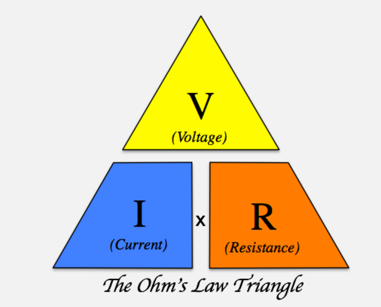
Cover the value you want to calculate
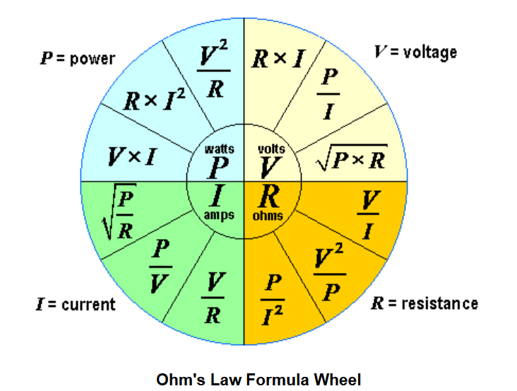
Complete electrical calculation reference
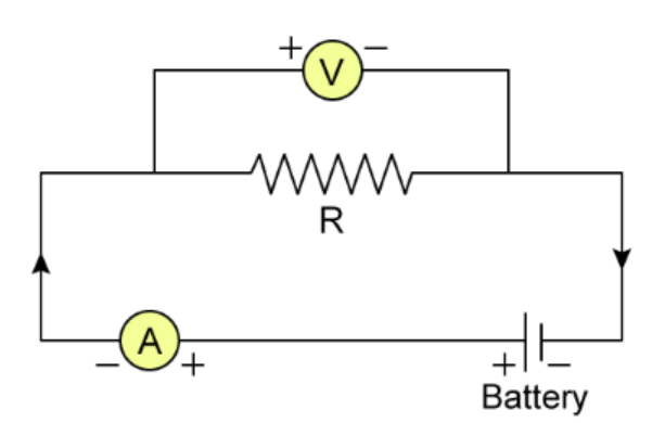
Real-world application example
Core Electrical Concepts
Voltage (V)
Electrical potential difference measured in volts. Represents the "pressure" that drives current through a circuit. Like water pressure in a pipe system.
Current (I)
Flow rate of electric charge measured in amperes. One ampere equals one coulomb of charge passing per second. Analogous to water flow rate.
Resistance (R)
Opposition to current flow measured in ohms. Depends on material, length, cross-section, and temperature. Conductors have low resistance.
Power (P)
Rate of energy transfer measured in watts. One watt equals one joule per second. Determines energy consumption and heat dissipation.
Complete Guide to Ohm's Law and Electrical Calculations
Ohm's Law represents the fundamental relationship in electrical engineering that governs how voltage, current, and resistance interact in electrical circuits. Developed by German physicist Georg Simon Ohm in 1827, this principle has become the cornerstone of electrical design, analysis, and troubleshooting.
Understanding the Mathematical Foundation
The Ohm's Law equation V = I × R establishes a direct proportional relationship between voltage (V) and current (I), with resistance (R) serving as the constant of proportionality. This mathematical relationship allows engineers and technicians to predict circuit behavior, select appropriate components, and ensure electrical safety.
Practical Applications in Modern Technology
Circuit Design and Analysis
Electrical engineers utilize Ohm's Law during the design phase of electronic devices. By calculating voltage drops across components, determining current requirements, and selecting resistor values, designers ensure optimal circuit performance. For instance, when designing LED circuits, engineers must calculate precise resistor values to limit current and prevent LED damage while maintaining proper brightness.
Troubleshooting Electrical Systems
Technicians apply Ohm's Law principles to diagnose electrical problems. By measuring voltage across components and calculating expected current values, they can identify faulty components, short circuits, or open circuits. This systematic approach reduces diagnostic time and improves repair accuracy in complex electrical systems.
Power Supply Design
Power supply engineers use Ohm's Law to calculate load requirements, determine wire gauges, and design voltage regulation circuits. Understanding the relationship between voltage, current, and resistance is crucial for creating efficient power distribution systems that minimize energy loss and heat generation.
Advanced Electrical Calculations
| Calculation Type | Formula | Application | Units |
|---|---|---|---|
| Voltage Calculation | V = I × R | Determine voltage drop across resistors | Volts (V) |
| Current Determination | I = V ÷ R | Calculate circuit current flow | Amperes (A) |
| Resistance Measurement | R = V ÷ I | Find unknown resistance values | Ohms (Ω) |
| Power Computation | P = V × I | Calculate energy consumption | Watts (W) |
| Power (Alternate) | P = I² × R | Determine heat dissipation | Watts (W) |
| Power (Alternate 2) | P = V² ÷ R | Calculate power from voltage | Watts (W) |
Real-World Examples and Calculations
Example 1: Residential Lighting Circuit
Consider a household lighting circuit with a 120V power supply and a 60W incandescent bulb. Using Ohm's Law calculations:
- Current: I = P ÷ V = 60W ÷ 120V = 0.5A
- Resistance: R = V ÷ I = 120V ÷ 0.5A = 240Ω
- Power Consumption: 60W (given)
Example 2: Automotive Electrical System
In a 12V car electrical system with a headlight drawing 4A of current:
- Power: P = V × I = 12V × 4A = 48W
- Resistance: R = V ÷ I = 12V ÷ 4A = 3Ω
- Energy per hour: 48W × 1h = 48Wh
Example 3: Electronic Device Power Supply
A laptop charger rated at 19V, 3.42A:
- Power Output: P = 19V × 3.42A = 65W
- Theoretical maximum current at 120V input: I = 65W ÷ 120V = 0.54A
Factors Affecting Electrical Resistance
Material Properties
Different materials exhibit varying resistance characteristics. Copper, with its excellent conductivity (1.68 × 10⁻⁸ Ω·m), serves as the standard for electrical wiring. Silver offers even lower resistance but at higher cost. Aluminum provides a cost-effective alternative with slightly higher resistance. Understanding material resistivity enables proper wire selection for specific applications.
Temperature Effects
Resistance changes with temperature according to the formula: R₂ = R₁[1 + α(T₂ - T₁)], where α represents the temperature coefficient. Most metals exhibit positive temperature coefficients, meaning resistance increases with temperature. This phenomenon explains why incandescent bulbs draw more current when first turned on, as their filament resistance increases dramatically when heated.
Geometric Considerations
The resistance of a conductor depends on its length (L) and cross-sectional area (A) according to: R = ρL/A, where ρ represents resistivity. Doubling conductor length doubles resistance, while doubling cross-sectional area halves resistance. This principle guides wire sizing decisions in electrical installations.
Safety Considerations and Best Practices
Current Limiting for Component Protection
Ohm's Law enables precise current limiting for sensitive electronic components. For LED protection, engineers calculate series resistor values using: R = (V_source - V_LED) ÷ I_LED. This prevents excessive current that could damage the LED while ensuring proper illumination.
Fuse and Breaker Sizing
Circuit protection devices require careful sizing based on expected current. Using Ohm's Law, engineers calculate maximum expected current and select protection devices with ratings slightly above normal operating current but below dangerous levels that could cause wire heating or fire hazards.
Voltage Drop Calculations
In long wire runs, voltage drop becomes significant. The formula V_drop = I × R_wire helps determine if wire gauge provides adequate voltage at the load. Excessive voltage drop can cause equipment malfunction, making these calculations essential for proper system design.
Advanced Applications and Extensions
AC Circuit Analysis
While Ohm's Law originally described DC circuits, it extends to AC circuits through impedance (Z). The AC form becomes V = I × Z, where Z represents complex impedance combining resistance, inductive reactance, and capacitive reactance. This extension enables analysis of alternating current systems including motors, transformers, and power distribution networks.
Nonlinear Circuit Elements
For nonlinear components like diodes and transistors, Ohm's Law applies differently. These devices exhibit varying resistance based on voltage or current, requiring more advanced analysis techniques. However, the fundamental relationship between voltage, current, and resistance remains applicable within specific operating regions.
Educational Value and Learning Resources
Ohm's Law serves as the foundation for electrical education worldwide. From introductory physics courses to advanced electrical engineering programs, students master these fundamental relationships before progressing to more complex topics. Interactive tools like this calculator enhance learning by providing instant feedback and visualization of abstract concepts.
Laboratory Applications
In educational laboratories, students verify Ohm's Law experimentally by measuring voltage and current across resistors of known values. These hands-on experiences reinforce theoretical understanding and develop practical measurement skills using multimeters, power supplies, and circuit prototyping equipment.
Professional Development
Electrical professionals regularly apply Ohm's Law in their daily work. Whether designing circuit boards, troubleshooting industrial equipment, or installing electrical systems, these fundamental calculations ensure safety, efficiency, and reliability in electrical installations.
Future Developments and Industry Trends
As electrical technology advances, Ohm's Law remains relevant in emerging fields. From nanoelectronics to renewable energy systems, the fundamental relationship between voltage, current, and resistance continues to guide innovation. Smart grid technologies, electric vehicle charging systems, and IoT devices all rely on these basic principles for efficient operation and design optimization.
The integration of computational tools with Ohm's Law principles enables more sophisticated circuit simulations, predictive maintenance algorithms, and automated design optimization. These advancements promise to enhance electrical system efficiency, reliability, and safety across all sectors of the electrical industry.
Frequently Asked Questions
Test Your Electrical Knowledge
Interactive Quiz Available
Test your understanding of Ohm's Law with our interactive quiz. Complete the quiz to assess your electrical circuit knowledge.